


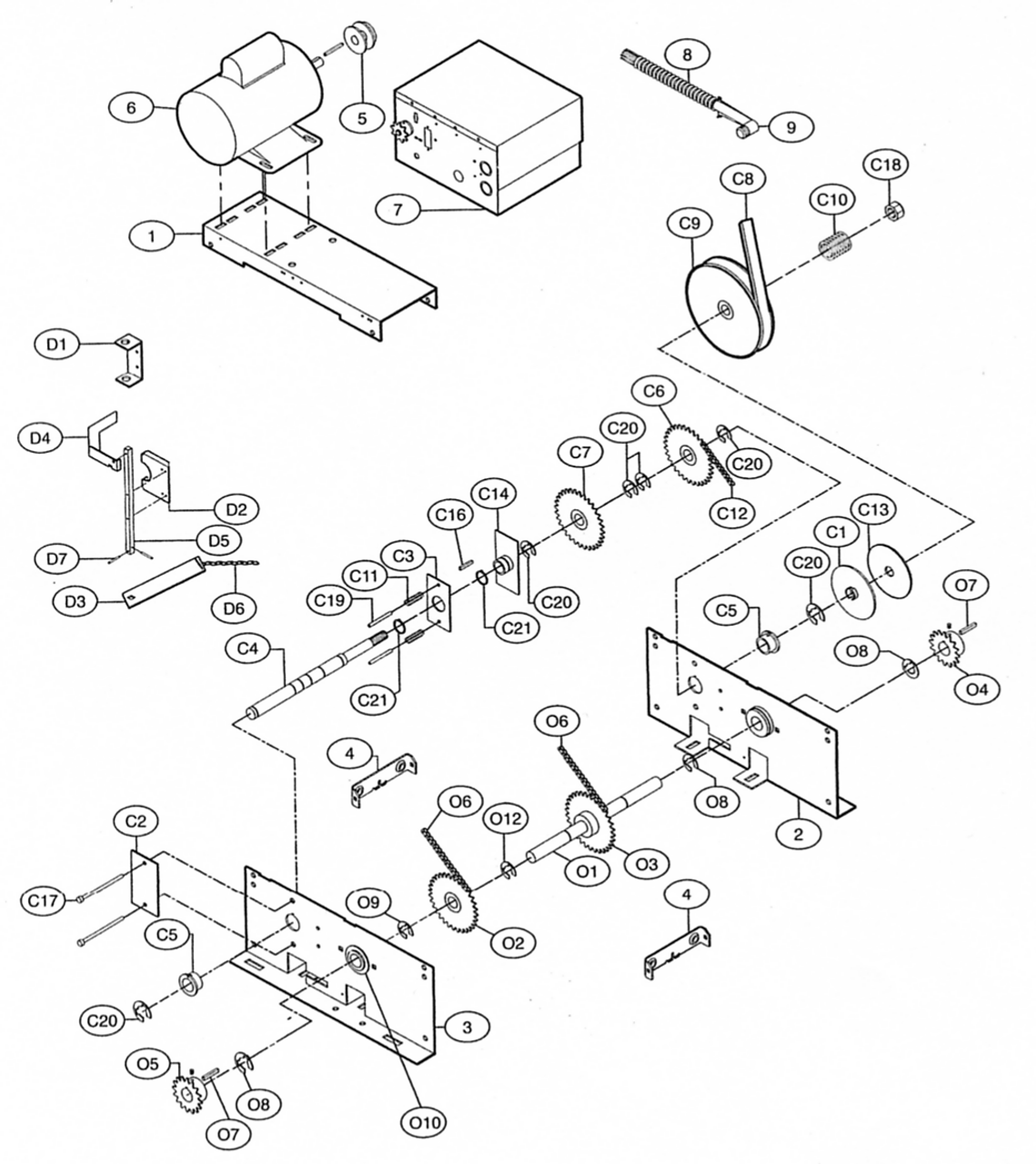
J Model Jackshaft Operator Parts — Prior to 2005
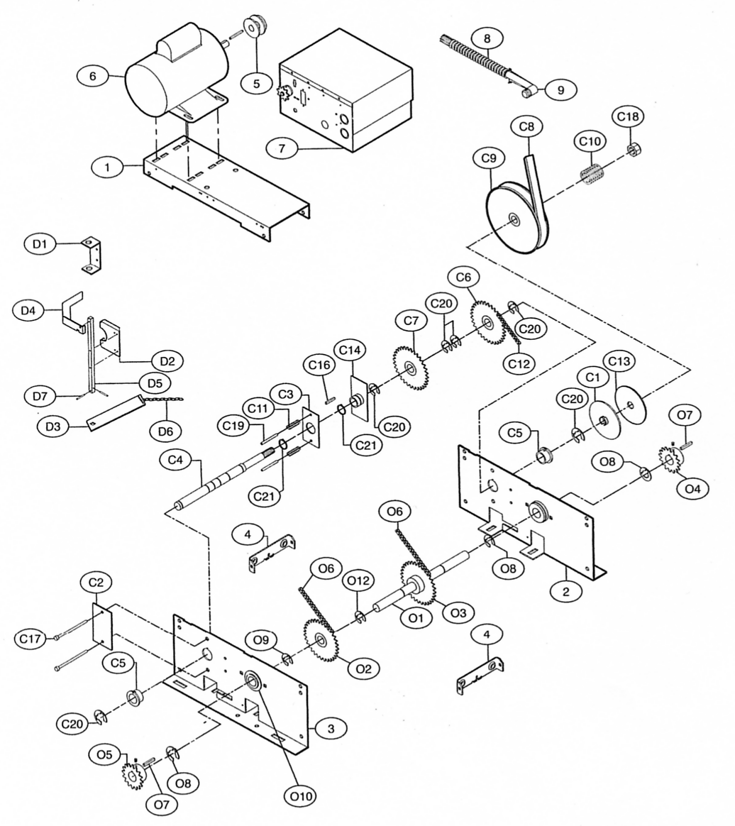
LiftMaster J Replacement Parts — Industrial-Duty Jackshaft Operator, Prior to 2005
Genuine replacement parts for the pre-2005 J series industrial-duty jackshaft operator, including the CJ carwash versions. These are the original side-plate frame machines built before LiftMaster redesigned the J in 2005. Use the exploded diagram to identify your part by its key number, then match it to the tables below.
Check your build date before ordering. The pre-2005 J uses different side plates and a different clutch shaft from the current machine, and the parts do not interchange. If your operator was built in 2005 or later, use our J5011 & All J Series page instead.
Old numbers and current numbers. Many of these parts were renumbered with a K prefix when LiftMaster reorganised its catalog. We show the number stamped on the old part and note the current number beside it. Either one gets you the right item — the clutch shaft, for example, is stamped 11-10920 but ships today as K11-15604.
Models Covered
J501L5 (1/2 HP) and J331L5 (1/3 HP), plus the carwash versions CJ5011 (1/2 HP) and CJ1011 (1 HP) — all built prior to 2005
Main Assembly
| Ref | Part # | Description |
|---|---|---|
| 01 | 10-15569 | Motor Plate |
| 02 | 75-15012E | Side Plate, Left Hand (now K75-15012E) |
| 03 | 75-15013E | Side Plate, Right Hand (now K75-15013E) |
| 05 | 17-6014 | Motor Pulley (now K17-6014) |
| 05 | 15-50B12LGH | Sprocket, 50B12 x 1" Bore |
| 06 | K20-1075B-2P | Motor, 3/4 HP |
| 09 | 28-10219 | Connector, 90 Degree |
Motors
The motor’s part number is printed on the motor’s own data label. If you can reach it, read the number straight off the label — that is the most reliable way to order the right one.
| Ref | Part # | Description |
|---|---|---|
| — | K20-1075B-2P | Motor, 3/4 HP, 115/230V, 1PH |
| — | K20-1050B-2TP | Motor, 1/2 HP, 115/230V, 1PH, 60Hz |
| — | K20-1050B-2TLP | Motor, 1/2 HP, 115/230V, 1PH, TEFC |
Clutch Shaft Group
| Ref | Part # | Description |
|---|---|---|
| C1 | K10-10166 | Clutch Plate |
| C2 | K10-10166 | Clutch Plate — second plate |
| C4 | 11-10920 | Clutch Shaft (now K11-15604) |
| C5 | 12-10715 | Flange Bearing, 1" ID (now K12-10715) |
| C6 | K15-10885 | Idler Sprocket Assembly, 48B32/48B14 |
| C8 | K16-5L304 | V Belt, 5L x 30.4" |
| C9 | K17-10165 | Pulley, 7" |
| C10 | 18-10168 | Compression Spring, Clutch (now K18-10168) |
| C11 | 18-10931 | Compression Spring, Disconnect (now K18-10931) |
| C12 | 19-48047M | Chain, #48 x 47P with Master Link (now K19-48047M) |
| C13 | K39-10167 | Clutch Pad |
| C16 | 80-207-19 | Key, 1/4" x 1/4" x 1-1/2" |
| C17 | 80-PX10-28 | Screw, #10-32 x 3", Slotted Round Head |
| C18 | 84-SH-76 | Nut, 3/4"-16 (now K84-SH-76) |
| C19 | 86RP10208 | Roll Pin, 5/16" x 2-1/2" (now K86-RP10-208) |
| C20 | 87-E-100 | E-Ring, 1", Plated (now K158A0056) |
| C21 | 87-E-150 | External Snap Ring, Zinc Coated |
Output Shaft Group
| Ref | Part # | Description |
|---|---|---|
| O1 | K11-10879 | Output Shaft |
| O2 | 15-10885 | Sprocket Assembly, 48B32/48B14 (now K15-10885) |
| O3 | K15-48B32LXX | Sprocket, 48B32 (no longer available) |
| O4 | 15-48B18LGE | Sprocket, #48B18 x 1" Bore |
| O6 | 19-48047M | Drive Chain, #48 x 47P with Master Link (now K19-48047M) |
| O7 | 80-207-19 | Key, 1/4" x 1/4" x 1-1/2" |
| O8 | 87-E-100 | E-Ring, 1", Plated (now K158A0056) |
| O10 | K12-10891 | Flange Ball Bearing |
Disconnect Group
| Ref | Part # | Description |
|---|---|---|
| D1 | 10-10707 | Disconnect Support Bracket |
| D2 | 10-10708 | Yoke |
| D3 | 10-10875 | Disconnect Lever (no longer available) |
| D4 | 10-10898 | Interlock Switch Actuator |
| D5 | 11-10878 | Disconnect Shaft |
| D6 | 19-8A-12 | Sash Chain, 12' (now 71-199010) |
| D7 | 86-RP04-100 | Roll Pin, 1/8" x 1" (now K86-RP04-100) |
Limit Assembly
| Ref | Part # | Description |
|---|---|---|
| — | K72-12897 | Limit Shaft and Sprocket |
| — | K80-202-24 | Washer |
Service Kits
Where a whole sub-assembly has worn, these kits supply the group complete and are usually the better buy.
| Ref | Part # | Description |
|---|---|---|
| — | K72-12532 | Output Shaft Kit |
| — | K72-12558 | Disconnect Assembly Kit, Right Hand |
Electrical Box — Which One Do I Have?
Pre-2005 J operators shipped with one of three control generations. Open the box and look at what is inside — that tells you which parts list to use. The three share very little.
| What you will see inside | Use this section | |
|---|---|---|
| — | A contactor and a thermal overload. No circuit board of any kind. | Contactor Style — the oldest |
| — | A contactor and overload, plus a small RPM sensor board. Still no logic board. | Logic Version 2 |
| — | A full green logic board with a coaxial antenna lead and plug-in relays. | Logic Version 3 — the newest pre-2005 |
Units built in 2005 or later use Logic 4.0 or Logic 5.0 and are covered on our J5011 & All J Series page.
Electrical Box — Contactor Style (Mechanical)
The original control, with no logic board at all. The overload must match your motor’s full-load amps — read the amp rating off the motor data label and pick the band that contains it. Fixed-value overloads are listed first, adjustable ones after.
| Ref | Part # | Description |
|---|---|---|
| 1 | K03-8024-K | Mini Contactor, 24V |
| 2 | 10-10020M1 | E-Box — H, J, T |
| 3 | 10-10115X | E-Box Cover (now K75-10128) |
| 3 | K75-10128 | E-Box Cover, Low Profile |
| 3 | 10-13899 | E-Box Cover, Cube (now K75-14347) |
| 4 | 21-5115 | Transformer, 115V (now K21-5115) |
| 4 | 21-5230 | Transformer, 230V (now K21-5230) |
| 4 | K21-5460 | Transformer, 380-460V |
| 5 | 23-10916 | Interlock Switch, SPDT (now K23-10916) |
| 6 | 24-24-1 | Relay, 24VAC, DPDT (now K24-24-1) |
| 7 | 24-115-1 | Relay, 115V (now K24-115-1) |
| 7 | 24-230-5 | Relay, 230V (now K24-230-5) |
| 8 | 25-2006 | Overload, 6A (now K25-2006) |
| 8 | 25-2008 | Overload, 8A (now K25-2008) |
| 8 | 25-2010 | Overload, 10A (now K25-2010) |
| 8 | 25-2015 | Overload, 15A (now K25-2015) |
| 8 | 25-2020 | Overload, 20A (now K25-2020) |
| 9 | 25-4002-5K | Overload, adjustable 1.6-2.5A (now K25-4002-5K) |
| 9 | 25-4004-K | Overload, adjustable 2.5-4.0A |
| 9 | 25-4003-K | Overload, adjustable 2.6-3.7A (now K25-4003-K) |
| 9 | 25-4008-K | Overload, adjustable 5.5-8.0A |
| 9 | 25-4011-5K | Overload, adjustable 8.0-11.5A |
| 10 | 42-10040 | Terminal Block, Radio (now K42-10040) |
| 11 | K42-110 | Terminal Block, 10 Position |
| 12 | 25-3000-K | Overload Bracket |
| L1 | 11-10021 | Limit Shaft (now K11-10021) |
| L3 | K13-10024 | Limit Nut |
| S3 | K23-10041 | Limit Switch |
| — | K72-12510 | Limit Shaft Kit |
| — | K75-12511 | Limit Switch Assembly |
| — | 71-2954029 | Light Delay Kit |
Electrical Box — Logic Control Version 2
The intermediate control — still a contactor and overload, but with an RPM sensor board added. Match the overload to your motor’s full-load amps as above.
| Ref | Part # | Description |
|---|---|---|
| 1 | 10-13790 | E-Box |
| 1 | 10-13792 | E-Box, Cube (no longer available) |
| 2 | 10-10115 | E-Box Cover (now K75-10128) |
| 2 | 10-13899 | E-Box Cover, Cube (now K75-14347) |
| 3 | 21-14182 | Transformer, 115/230V (now K21-14182) |
| 3 | K21-5460 | Transformer, 460V |
| 4 | 25-13842 | Overload, 1.4-2.0A (no longer available) |
| 4 | 25-13840 | Overload, 2.0-3.0A |
| 4 | 25-10296 | Overload, 2.8-4.4A |
| 4 | K25-2006 | Overload, 6A |
| 4 | K25-2008 | Overload, 8A |
| 4 | 25-2010 | Overload, 10A (now K25-2010) |
| 4 | 25-2015 | Overload, 15A (now K25-2015) |
| 4 | K25-2020 | Overload, 20A |
| 6 | K42-10040 | Terminal Block |
| 7 | K79-15016-1 | RPM Sensor Assembly |
| A1 | K23-10916 | Interlock Switch |
| L1 | 11-10021 | Limit Shaft (now K11-10021) |
| L1 | K11-13361 | Limit Shaft |
| L3 | K13-10024 | Limit Nut |
| S5 | K23-10041 | Limit Switch |
| — | 03-8024-D | Contactor |
| — | 75-12514 | Limit Switch Kit, S1-S7 (now K72-12515-1) |
| — | 71-2954029 | Light Delay Kit |
Electrical Box — Logic Control Version 3
The last pre-2005 control, and the first with a true logic board.
| Ref | Part # | Description |
|---|---|---|
| 1 | K75-32269 | E-Box Cover |
| 2 | 21-14182 | Transformer, 115/230V (now K21-14182) |
| 2 | K21-35057 | Transformer, 460V |
| 2 | 21-35077 | Transformer, 575V (now K21-35077) |
| 3 | 29-31244 | Relay, 24VDC, DPST — A and B relay (now K29-31244) |
| 4 | 29-31229 | Relay, 24VDC, SPDT — C relay, single phase only (now K29-31229) |
| 4 | 29-31245 | Relay, 12VDC, SPDT — C and D relay, three phase only (now K29-31245) |
| 5 | K74-31243 | MOV, 508V |
| 6 | K79-15016-1 | RPM Sensor Assembly |
| 7 | K001A5729 | Logic Board, L3 (no longer available) |
| 8 | K2A761 | Receiver Coaxial Cable (now K002A0761) |
| 9 | K001C3196-3 | Antenna, 315MHz |
| 10 | K13-10024 | Limit Nut |
| 11 | K23-10041 | Limit Switch, SPDT |
| 11 | K23-10041-1 | Limit Switch, Double Pole |
| 12 | 42-31247 | Terminal Block (now K42-31247) |
| 13 | K42-10040 | Terminal Block, Radio |
| K1 | K72-14130-1 | Limit Shaft Kit |
| K2 | K72-12515-1 | Limit Switch Kit |
| — | K74-MODELH | Main Wiring Harness |
Not sure which part you need? Send us the number stamped on the old part along with your operator's model and serial number and we will confirm the current equivalent before you order.